






Phòng trưng bày đường ống ngầm toàn diện đúc sẵn quá trình sản xuất linh kiện chi tiết
Đầu tiên, cài đặt địa điểm
Trang web đúc sẵn
1. Trang web được lựa chọn theo tình hình thực tế của dự án. Các trang web thông qua quản lý đóng cửa để thiết lập nhập khẩu và xuất khẩu, và con đường tiếp cận xây dựng được dành riêng trong khu vực lập kế hoạch trang web, và các dấu hiệu khác nhau được treo tại xuất nhập khẩu theo quy định.
2. Bố cục của nhà máy đúc sẵn phải tuân thủ nghiêm ngặt các yêu cầu của nhà máy tiêu chuẩn, đáp ứng các yêu cầu về an toàn và sức khỏe nghề nghiệp và hệ thống quản lý môi trường và hướng dẫn vận hành HSE và thiết lập các cơ sở bảo vệ môi trường an toàn. Nó sẽ được trang bị đầy đủ để đáp ứng các yêu cầu về sản xuất an toàn và văn minh, xả nước thải và xử lý rác thải. Theo đúng các quy định có liên quan của các cơ quan chính quyền địa phương.
3. Làm sạch trang web đúc sẵn, san lấp mặt bằng, rung và đầm nén, đặt một đế xi măng ổn định dày 20cm, làm mịn và rung và nén. Con đường chính của nhà máy sẽ đổ bê tông thương mại C20 dày 15cm trên nền xi măng macadam ổn định. , khu vực lắp đặt, tiền chế, khu vực sản xuất, phòng trưng bày ống tích hợp khu vực bảo tồn thiên nhiên đổ bê tông thương mại 10cmC20. Tại vị trí lắp đặt giàn cần cẩu, chiều sâu đào là 60cm, và bê tông được đổ và đường ray được đặt. Cũng làm ba điều sau:
(1) Trang web cần phải được làm sạch và san lấp mặt bằng, bao gồm các vị trí đúc sẵn, kết nối các vành đai công trình xây dựng và các đường giao thông hiện có, và các lối đi trong các khu vực đúc sẵn.
(2) Trong khu vực đúc sẵn, đá, cỏ dại, cây cối, cấu trúc, vv ảnh hưởng đến đoạn đường hoặc công trình xây dựng của máy móc xây dựng nên được làm sạch, mương và sườn núi phải được san bằng và các khu vực trũng thấp với nước tích lũy nên được ráo nước và đầy, nếu cần thiết, thay đổi. Điền vào, hoàn toàn đảm bảo độ phẳng của mặt đất và khả năng chịu tải và nén.
(3) Vệ sinh và san lấp mặt bằng trước khi chế tạo phải được thực hiện để tiết kiệm đất hoặc chiếm đất, không có tắc nghẽn giao thông, không gây thiệt hại cho các tòa nhà, cơ sở vật chất, di tích, vv để ngăn ngừa ô nhiễm môi trường và xói mòn đất.
4. Prefabrication của khu vực chế biến và lắp đặt thanh thép, tích hợp phòng trưng bày sản xuất ống đúc sẵn, phòng trưng bày ống tích hợp kho bảo tồn thiên nhiên, khu vực lưu trữ thư viện tích hợp và các khu chức năng khác. Khu vực văn phòng và khu vực sinh hoạt được thiết lập theo tình hình thực tế, và lối vào và lối ra trường được đúc sẵn được thiết lập như một phòng bảo vệ. Thứ hai, quá trình sản xuất
Biểu đồ quy trình sản xuất
1. Củng cố kỹ thuật vật liệu xây dựng vào trang web, kiểm tra lấy mẫu, chế biến thép, thanh thép ràng buộc, lắp đặt.
(1) Kiểm tra tiếp cận cốt thép a. Thanh cốt thép là thép cán nóng HPB300 và thép thanh HRB400 cán nóng. Sức mạnh tiêu chuẩn của thanh thép đáp ứng các yêu cầu của 4.2.2 GB50010-2010. Thanh thép gân phù hợp với cốt thép cho bê tông cốt thép: Phần II: Thanh thép cán nóng (GB1499.2-2007); các thanh thép tròn sáng đáp ứng các yêu cầu về thép cho bê tông cốt thép: Phần I: Thanh thép cán nóng (GB1499.1-2008). Tấm thép được làm bằng thép Q235-B, điện cực hàn Thép hàn HPB300 được hàn với điện cực loại E43, và thép mạ HRB400 được hàn với điện cực loại E55. b. Trước khi thép vào khu vực, kiểm tra tính đa dạng, cấp, đặc điểm kỹ thuật, số lượng và danh sách vật liệu theo đúng yêu cầu, cho dù chứng nhận chất lượng sản phẩm, báo cáo kiểm tra nhà máy và báo cáo kiểm tra lại đầy đủ và hợp lệ. Kiểm tra tính chất cơ học phải phù hợp với các tiêu chuẩn liên quan. c. Trước khi thép đi vào hiện trường và trước khi sử dụng, kiểm tra chất lượng bề mặt của thanh thép, cho dù là thẳng, không bị hư hại, không xỉ xỉn trên bề mặt, da nặng, vết nứt, vết dầu, dạng hạt hoặc gỉ cũ, màu đồng nhất , xem đường kính của thanh thép Đáp ứng các yêu cầu, để không ảnh hưởng đến sức mạnh của thép và hiệu suất neo đậu. Thép tấm, que hàn, vv được kiểm tra với các thanh kiểm tra thanh thép trước khi vào trang web.
(2) Bảo quản thép thanh a. Các thanh thép vào trang web được lưu trữ trong khu vực lưu trữ thanh thép theo sự đa dạng, đặc điểm kỹ thuật và cấp. Các tài liệu được lưu trữ bởi các nhân viên vật chất và người giám hộ. Thanh thép được yêu cầu phải được che bằng một miếng đệm để ngăn ngừa rỉ sét. b. Kiểm tra xem thanh thép có chứng nhận nhà máy và báo cáo kiểm tra nhà máy và báo cáo kiểm tra lại hay không. Kiểm tra chất lượng xuất hiện và đường kính đại diện thể tích. Thanh thép phải được kiểm tra toàn diện về chỉ số chất lượng của nó. Theo kiểm tra hàng loạt, đường kính và độ lệch trọng lượng giống với cùng một nhà máy, cùng một số lò, cùng đặc điểm kỹ thuật, cùng quy trình sản xuất và thanh thép 60 tấn vào cùng một công trường xây dựng cùng một lúc một lô kiểm tra, dưới 60 tấn. Cũng như một lô thử nghiệm, thực hiện lấy mẫu chứng kiến. Việc lấy mẫu thanh thép phải được thực hiện bởi kỹ sư giám sát. Hai thanh thép được lấy để lấy hai mẫu thử kéo, mỗi miếng có chiều dài khoảng 450 mm, và hai mẫu thử uốn nguội có chiều dài khoảng 350 mm, được đặt trong hộp kiểm tra, và sau đó được giám sát để niêm phong hoặc giám sát phòng thử nghiệm. Nếu kết quả của báo cáo kiểm tra lại không đủ tiêu chuẩn, nó sẽ được lấy mẫu kép và kiểm tra lại. Kết quả của báo cáo kiểm tra lại phải đủ điều kiện và kỹ sư giám sát chuyên nghiệp sẽ ký phê duyệt và có thể sử dụng hàng loạt thanh thép trong chế biến. Lưu trữ và bảo quản các vật liệu khác phải được thực hiện bằng phương pháp cách ẩm.
(3) Chế biến cốt thép Trước khi xử lý, theo thông số kỹ thuật thiết kế và chiều dài và số lượng, kết hợp với các kỹ thuật gia công khác nhau, chiều dài của mỗi thanh cốt thép được xác định bằng cách tính toán để đảm bảo độ chính xác. Trong khi xử lý, kiểm tra xem có bất kỳ lỗi hoặc thiếu sót nào trong bảng xóa. Kiểm tra bảng vật liệu cho từng loại thanh thép. Sau hai lần kiểm tra này, nhấn bảng vật liệu để giải phóng mẫu thực. Sau khi sản xuất thử nghiệm đủ điều kiện, nó có thể được xử lý theo lô. Thanh thép tốt nên được xếp chồng lên nhau gọn gàng và có trật tự. Bề mặt của thanh thép phải sạch, và dầu mỡ, bụi bẩn và gỉ phải được làm sạch trước khi sử dụng. Các thanh thép được làm thẳng và làm thẳng cơ học. Các thanh thép sau khi làm thẳng không được uốn cục bộ, uốn cong hoặc sóng nhỏ. Việc cắt thanh thép phải dựa trên số thanh thép, đường kính, chiều dài và số lượng. Chiều dài và chiều dài của thanh thép nên bị phá vỡ và vật liệu ngắn nên bị hỏng đầu tiên, và đầu thép ngắn nên được giảm và rút ngắn càng nhiều càng tốt để tiết kiệm thép và giảm tổn thất. Khi thanh thép bị uốn cong, phần đầu ra xác định điểm uốn và xác định góc uốn dựa trên cường độ hồi phục của mỗi thanh thép. Trước khi uốn chính thức, các thanh thép đã bị uốn cong với số lượng lớn sẽ bị uốn thử và các dữ liệu kỹ thuật liên quan sẽ được xác định trước khi uốn mẻ. Sau khi thanh thép bị uốn cong, cung tròn tạo thành một vòng cung. Sau khi uốn, kích thước không lớn hơn kích thước làm trống. Giá trị điều chỉnh uốn cần được xem xét. Đường kính uốn D của thanh thép cong và phần uốn cong của phần giữa không nhỏ hơn 5 lần đường kính của thanh thép. Chiều dài của thanh thép nên được xem xét một cách toàn diện theo kích thước của thành phần, độ dày của lớp bảo vệ và giá trị điều chỉnh uốn của thanh thép. Độ lệch cho phép của chế biến thanh thép không được vượt quá đặc điểm kỹ thuật. Đối với các thanh thép không đủ vật liệu hoàn thành, phương pháp hàn áp lực khớp mông được sử dụng để uốn chiều dài chân và sau đó uốn cong. Các thợ hàn mông phải được đào tạo trong một quá trình hàn mông đặc biệt và lấy mẫu để kiểm tra. Sau khi các thanh thép khác nhau được hình thành, độ lệch cho phép không được vượt quá đặc điểm kỹ thuật: chiều dài đầy đủ của các sườn buộc phải là ± 10 mm; độ lệch của chiều dài của mỗi phần của bàn đạp là ± 5 mm; độ lệch của các mép cong sẽ là ± 20 mm của thành viên, khối lượng lớn Bê tông là ± 30mm; độ lệch của góc thép là 3mm; các sườn tròn 6 ~ 12mm được làm thành bàn đạp, và chiều dài của móc cuối là 75 ~ 105mm theo đường kính của sườn chính. Tính toán cụ thể trước khi tẩy trống được xác định, các thanh thép đã được xử lý được phân loại và lưu trữ, và các thanh thép hình thành được ngăn không bị biến dạng trong quá trình lưu trữ và vận chuyển.
Ván khuôn thép (cốt thép)
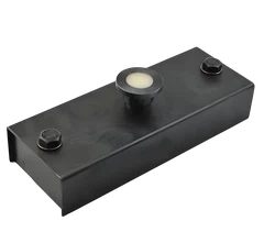
Khó khăn: Khó khăn trong việc tạo ra các xương sườn chính của ống hình chữ nhật là xương sườn sườn bên ngoài. Mỗi vòng bao gồm bốn thanh thép với hai vòng cung mỗi hình thành một vòng thép hình chữ nhật trên ống hình chữ nhật. Bán kính của vòng cung quá nhỏ, đoạn cung cong ngắn và độ chính xác cao. . Giải pháp: Trước khi các thanh thép được uốn cong, đánh dấu chúng tại giao điểm của mỗi cung. Sau đó, vòng cung độ R90 bị cong bởi uốn ba cuộn và đoạn thẳng không bị cong. Sau khi vòng cung được uốn cong hoàn toàn, nó được đặt vào kiểm tra tổng thể tiêu chuẩn. Sau khi các yêu cầu được đáp ứng, dấu vị trí chuyển động của bánh xe di chuyển được thực hiện trên nền tảng vận hành máy uốn để sản xuất nhanh chóng tiếp theo. Máy uốn ba cuộn cần có chức năng chạy bộ và đảo chiều. (4) Thanh thép hàn Thanh thép hình thành được đặt trên thanh công cụ hàn thép thanh theo bản vẽ thi công để hàn. Chất lượng hàn là một phần quan trọng để đảm bảo sức mạnh tổng thể của thanh thép. Trong nhà máy chế biến thép thanh, các thanh thép chủ yếu được làm sạch bằng cách hàn hai mặt flash hàn để làm sạch các gờ góc và lớp gỉ mặt, vết bẩn dầu và màng oxit trước khi hàn, và ánh kim loại bị phơi ra bởi mài, và không có hiện tượng oxy hóa. Đồng thời, mặt cuối của thanh thép nên được làm phẳng để tạo điều kiện kết hợp tốt. Các đồ đạc trên cả hai mặt phải được căn chỉnh để đảm bảo rằng hai thanh thép nằm trên cùng một trục và độ hở cục bộ của hai thanh thép không quá 3 mm. Áp lực trong quá trình hàn phải đồng nhất và mạnh mẽ, và nhiệt độ phải được kiểm soát ở 30-40 MPa tùy thuộc vào đường kính của thanh thép để đạt được độ bám dính tốt giữa hai thanh thép. Khi các thanh thép có đường kính khác nhau được hàn mông, độ lệch không được vượt quá 7mm. Hàn mông và hàn điểm là đúng theo quy định, và các nhân viên hàn được chứng nhận để làm việc. Sau khi hàn xong, khớp sẽ được thay đổi từ màu trắng sang màu đen để nhả kẹp, và thanh thép sẽ được lấy ra một cách trơn tru để tránh bị uốn cong. Sau khi hàn xong các thanh thép, việc kiểm tra sự xuất hiện của các mối nối hàn phải được thực hiện đúng thời gian và các mối nối không kiểm tra bằng mắt sẽ được hàn lại. Tất cả các máy hàn phải đảm bảo rằng tất cả các loại máy hàn đều ở trong tình trạng hoạt động tốt, chủ động hiệu suất chính và các thông số của các máy hàn khác nhau và lựa chọn các thông số tốt nhất cho hoạt động thực tế theo các điều kiện của kim loại cơ bản và thời tiết để đảm bảo chất lượng hàn. . (5) Cốt thép cốt thép nên được hiệu chỉnh lại trước khi đặc điểm kỹ thuật, kích thước, hình dạng, số lượng, công cụ định vị, vv, và kiểm tra toàn diện phải được thực hiện theo bản vẽ thiết kế và danh sách thành phần. Thiết kế, danh sách thành phần và đối tượng vật lý có thể được kết hợp. Bảo vệ. Trước khi hệ thống được cài đặt, cốt thép được bố trí trên nền tảng dụng cụ định vị theo dữ liệu thiết kế. Đồng thời, theo vị trí, các thiết lập của gia cố đứng được xác định để đảm bảo rằng các thanh thép sau khi cài đặt đáp ứng các yêu cầu. Trong quá trình bảo mật, các thanh thép chủ yếu được làm bằng dây ràng buộc và hàn điểm. Các lỗ được làm từ 20 ~ 22 # dây. Phương pháp ràng buộc và ràng buộc phù hợp với các thông số và quy định. Hàn điểm được sử dụng chủ yếu để tạo thành thanh thép và thanh đứng. Việc sửa chữa, hàn điểm phải chắc chắn, các điểm phải được phân bố đồng đều, và các sườn lực không nên bị hư hỏng nghiêm trọng. Khớp nối của thanh thép phải đáp ứng các yêu cầu sau: a. Sự kết thúc của chiều dài vòng không được nhỏ hơn 10 lần đường kính của thanh thép ở uốn cong của thanh thép, và khớp không được đặt tại thời điểm uốn tối đa của bộ phận. b. Trong vùng căng thẳng, phần cuối của khớp nối bằng thép cấp I sẽ được làm thành một cái móc. Trong cùng một phần, diện tích mặt cắt của khớp của vùng căng thẳng phải nhỏ hơn 50% tổng diện tích của khớp tiếp nhận lực và khớp nối không được lớn hơn 50%. Không quá 25%, đồng thời, các khớp lashing không được vượt quá 50% trong vùng nén. c. Các khớp nối cốt thép, gắn với dây ở trung tâm và ở cả hai đầu. d. Các vị trí khớp của các xương sườn căng thẳng được so le nhau. Độ dài vòng của khớp nối cốt thép bị căng nên đáp ứng các yêu cầu thiết kế kết cấu. Các khớp nối thép hàn và khớp nối cơ học nên được đặt ở thời điểm uốn tối thiểu và so le. e. Khi đường kính của thanh thép nhấn mạnh là ≥25mm, không nên sử dụng mối nối không hàn. f. Độ dày của lớp bê tông bảo vệ của thanh thép nhấn mạnh phải đáp ứng các yêu cầu thiết kế kết cấu. Để đảm bảo vị trí chính xác của thanh thép, nó được gắn và lắp đặt theo các yêu cầu thiết kế. g. Trong quá trình ràng buộc lồng cốt thép, một ống ΦPVC được chôn trước trên bốn mặt của khớp, Φ14mm, chiều dài của ống PVC được xác định theo độ dày thành của miệng của mối nối và PVC được nhúng sẵn ống được sử dụng như lỗ kiểm tra và lỗ phun. Các lỗ nâng được lắp đặt ở 500mm phía trên và bên dưới trục trung tâm của các cạnh trái và phải của phòng trưng bày ống tích hợp. Hai ống thép Φ125 * 10mm * 220mm được hàn vào khung thép, và tấm thép Φ140 * 4 được sử dụng để hàn kín. Ống thép Φ125 * 10mm * 180mm được lắp đặt trước khi nâng. Iron110mm * 350mm pin sắt được sử dụng như tai móc ống tích hợp để đáp ứng việc xây dựng cẩu của phòng trưng bày ống tích hợp. Công trình cốt thép là những dự án được che giấu. Trước khi đổ bê tông, các thanh thép và các bộ phận nhúng phải được kiểm tra và chấp nhận, và các bản ghi kỹ thuật ẩn phải được thực hiện. Sau khi các kỹ sư giám sát tại chỗ đồng ý, quá trình tiếp theo có thể được thực hiện.
Lắp ráp khuôn thép
Phương pháp hiệu quả nhất cho quá trình lắp ráp nên là: đầu tiên hỗ trợ khuôn bên trong, xương sườn kết nối thép nên được hàn đầu tiên và sau đó được đặt trong khuôn dưới cùng, và vòng thép kết nối xương sườn của ổ cắm sẽ được hàn sau thép khung được đưa vào khuôn, và các thanh thép được hàn. Sau khi bộ xương được đưa vào khuôn, lỗ vữa, lỗ vữa và tấm thép được nhúng sẵn được hàn. Sau khi hàn, khuôn ngoài được lắp ráp. Để ngăn chặn vị trí của lỗ nâng không chính xác, lỗ nâng được cố định trên khuôn ngoài, và khuôn ngoài được lắp ráp và sau đó ổ cắm hàn được chuẩn bị trước. Chôn vòng thép. (6) Lớp bảo vệ cốt thép Lớp bê tông bảo vệ được làm bằng khối bê tông, độ dày bằng độ dày của lớp bảo vệ được thiết kế, kích thước khối là 3cm × 3cm, số pad lớn hơn cường độ vữa C25, và bảo dưỡng được tăng cường trong quá trình sản xuất để đạt được sức mạnh thiết kế. 85% số trên có thể được sử dụng. Khi được sử dụng trong cấu trúc thẳng đứng, đường kết dính 20 # có thể được chôn trong khối, và khối được gắn với thanh thép bằng dây. Lớp đáy của tấm đáy và lớp gia cường tường được đặt một mét vuông trên một mét vuông, và hoa mận được sắp xếp. Khoảng cách của các miếng đệm phải được mã hóa chính xác. Sắp xếp hợp lý các khối, và buộc chúng chặt chẽ trên các thanh thép căng thẳng, thay vì được đặt trên các gân không bị căng thẳng, việc sửa chữa nên được vững chắc để ngăn chặn sự dịch chuyển và trượt trong quá trình rót; cho dù các khối được kiểm tra đầy đủ trước khi đổ bê tông Thiếu hoặc hư hỏng. 2. đổ bê tông (1) vật liệu bê tông vận chuyển bê tông được vận chuyển đến các trang web đúc sẵn bằng tàu chở bê tông, và bơm vào kho bằng xe tải bơm bê tông. Sự sụt giảm bê tông thường được kiểm soát giữa 140 và 180 mm (giá trị cụ thể phụ thuộc vào nhiệt độ trong ngày). 4 thanh rung bê tông với bán kính dao động từ 20-25cm, do đó khoảng cách giữa mỗi thanh là 40cm. Mỗi chiều sâu của thanh là trong vòng 5cm bên dưới bề mặt rung trước đó, và thời gian dao động trên mỗi que là 2-3 phút. (2) Thiết kế tỷ lệ pha trộn và kiểm tra a. Thiết kế tỷ lệ pha trộn Để đáp ứng các yêu cầu về cường độ thiết kế bê tông, khả năng chống sương giá, độ thấm, tỷ lệ mở rộng cát tổng hợp và khả năng thi công, kiểm tra tối ưu hóa kết cấu xây dựng bê tông Đồng thời, nó đáp ứng các yêu cầu về tỷ lệ nước-xi măng xây dựng và sụt giảm, và được xem xét và phê duyệt bởi kỹ sư giám sát. Tỷ lệ pha trộn bê tông phải đảm bảo rằng bê tông thu được có thể đáp ứng các điều kiện đổ cụ thể, và mức tiêu thụ nước trong tỷ lệ trộn bê tông càng nhỏ càng tốt. b. Kế hoạch thử nghiệm tỷ lệ trộn bê tông thử nghiệm tỷ lệ trộn bê tông, bao gồm kiểm tra tỷ lệ trộn bê tông và kiểm tra hiệu suất bê tông của các loại cường độ khác nhau, tỷ lệ pha trộn thử nghiệm 14d trước các thành phần thử nghiệm tỷ lệ trộn khác nhau và trộn, đúc và bảo trì, vv được báo cáo cho kỹ sư giám sát. c. Kiểm soát tỷ lệ pha trộn xây dựng Theo thử nghiệm tỷ lệ hỗn hợp và danh sách lô được phê duyệt bởi kỹ sư giám sát, tỷ lệ trộn bê tông được kiểm soát và tổng lượng nước tiêu thụ được điều chỉnh theo hàm lượng nước của cốt liệu. Sự sụt giảm bê tông được xác định bởi bản chất của phần kết cấu, tốc độ gia cố, phương pháp vận chuyển bê tông và phương pháp đúc, và điều kiện khí hậu, và sử dụng độ sụt nhỏ càng nhiều càng tốt. Bê tông sụt giảm đáp ứng các yêu cầu của SL677-2014. (3) Thử nghiệm lấy mẫu bê tông Trong quá trình đổ bê tông, nhà thầu phải thực hiện thử nghiệm lấy mẫu bê tông tại khu vực xả và đổ theo quy định của SL352-2006 và hướng dẫn của người giám sát và gửi các tài liệu sau đây cho người giám sát : a. Và giấy chứng nhận chất lượng của phòng trưng bày ống tích hợp của nó; b. Chế phẩm, sự pha trộn và kích thước của mẫu thử; c. Mô tả chuẩn bị và bảo trì mẫu thử; d. Kết quả kiểm tra và mô tả; e. Bê tông ở các độ tuổi khác nhau Dữ liệu thử nghiệm như mật độ khối, cường độ nén, độ bền kéo, giá trị độ bền kéo, mô đun đàn hồi, tỷ lệ Poisson, độ sụt và thiết lập ban đầu và thời gian cài đặt cuối cùng. (4) đổ bê tông a. Tỷ lệ pha trộn bê tông thương mại phải đáp ứng các yêu cầu của DL / T5330-2005 "Đặc điểm kỹ thuật thiết kế cho tỷ lệ trộn bê tông thủy lực", và sử dụng xi măng và chất khử nước với thời gian cài đặt ban đầu tương đối sớm và tăng cường sức mạnh sớm sau khi thiết lập cuối cùng. Các chất phụ gia khác nhau như đại lý không khí và tác nhân cường độ sớm nên xem xét khoảng cách vận chuyển bê tông dài, tăng cường độ sớm của bê tông, giảm thời gian tháo dỡ, rút ngắn thời gian thi công và đặc biệt giải quyết sự tăng trưởng chậm của cường độ bê tông trong xây dựng mùa đông. . Vấn đề với sự sụt giảm cụ thể của công trường sẽ được kiểm soát ở mức 140-180mm. b. Sau khi khuôn mẫu và thanh thép đã được cài đặt và đủ điều kiện của các kỹ thuật viên để kiểm tra chất lượng và giám sát, và xác nhận, phòng trưng bày ống tích hợp có thể được đổ. Chiều cao của hố cao hơn 2m so với mặt đất, và độ sụt nhỏ hơn 2m. Các thùng chuỗi mềm được đặt ở miệng để đảm bảo rằng bê tông có chiều cao rơi xuống dưới 2m. c. Bê tông đường hầm bê tông ống phải áp dụng phương pháp đúc đối xứng để xem xét chiều cao của cạnh không được vượt quá 40cm và việc xây dựng bằng phương pháp đúc liên tục không nên gián đoạn. d. Bê tông được đổ trong các lớp, theo một hướng nhất định và với độ dày nhất định. Bê tông nằm ngang và lớp dày 30-40 cm. e. Rung sử dụng que rung cắm, khoảng cách di chuyển không vượt quá 1,5 lần bán kính tác động của thanh rung và duy trì khoảng cách từ khuôn mặt bên cạnh 5 đến 10 cm. Chèn lớp bê tông dưới 5 đến 10 cm khi rung và từ từ đề xuất thanh rung sau mỗi lần rung. Tránh rung ván khuôn, thanh thép, vv trong khi rung; cho mỗi phần rung, nó phải dao động cho đến khi bê tông được đầm chặt, đó là, bê tông dừng chìm, không có bong bóng xuất hiện, và bề mặt phẳng và bùn. Trong quá trình rót, mỗi loại công việc phải được bố trí để kiểm tra sự thay đổi của thanh thép, khung và giấy nến, và tình hình cần được xử lý kịp thời. 3, hộp bảo trì cống và demoulding
Hộp cống đúc sẵn
(1) Sau khi bê tông được đổ, sau khi bê tông được thiết lập ban đầu, bộ sưu tập ống tích hợp được hấp ở nhiệt độ cao. Quá trình hấp thông qua nắp hấp được tùy chỉnh và khuôn thư viện ống được tích hợp được đậy nắp hấp và phần đáy của nắp hấp được đóng kín để ngăn hơi nước thoát ra trong quá trình hấp. Nồi hấp được hấp cho cơ sở hấp thân thiện với môi trường. ủng hộ. Trong quá trình hấp, nó được chia thành bốn giai đoạn: tĩnh dừng, nóng lên, nhiệt độ không đổi và làm mát. Trong thời gian dừng tĩnh, nhiệt độ môi trường xung quanh nên được giữ dưới 5 ° C, và tăng nhiệt độ nên được kiểm soát trong vòng 15 ° C / h. Nhiệt độ không đổi: Khi nhiệt độ đạt đến 60 ° C, có thể dừng quá trình hấp sau bốn giờ hấp nhiệt độ không đổi. Làm mát: Tỷ lệ làm mát của phòng trưng bày ống tích hợp trong nhà kho hấp nhỏ hơn 10 ° C / h và nhiệt độ bề mặt của phòng trưng bày ống tích hợp không quá 5 ° C, sao cho bộ sưu tập ống tích hợp có thể được tháo ra khỏi nắp hấp. Trong quá trình hấp, nhân viên đặc biệt được sắp xếp để kiểm soát hiệu quả nhiệt độ tăng và giảm và ghi lại chi tiết. Thứ nhất, sau khi thư viện ống tích hợp đã được đổ và dừng lại trong 2 giờ, thư viện ống tích hợp đã được thiết lập ban đầu và việc kiểm tra không có bất thường. Nắp hấp và thiết bị được chuyển đến khu vực sản xuất đúc sẵn, và phòng trưng bày ống tích hợp đã được thiết lập với nắp hấp. Được niêm phong chặt chẽ, kiểm tra tình trạng niêm phong của thiết bị hấp và nắp hấp và gỡ lỗi thiết bị hấp. Sau khi chuẩn bị xong, bắt đầu thiết bị hấp để hâm nóng và chú ý kiểm soát tốc độ gia nhiệt trong vòng 15 ° C / h trong quá trình gia nhiệt. . Không được làm nóng quá nhanh hoặc quá chậm, điều này sẽ ảnh hưởng đến cường độ nén và hiệu suất của phòng trưng bày ống tích hợp. Khi nhiệt độ đạt đến 60 ° C, bắt đầu hấp nhiệt độ không đổi. Sau khi nhiệt độ không đổi hấp trong bốn giờ, có thể dừng quá trình hấp. Sau khi nhiệt độ không đổi được hoàn thành, phòng trưng bày ống tích hợp được làm lạnh và duy trì trong nhà kho hấp, và tốc độ làm mát được kiểm soát chặt chẽ. Trong vòng 10 ° C / h, nhiệt độ giảm xuống nhiệt độ bề mặt của phòng trưng bày ống tích hợp và nhiệt độ môi trường không vượt quá 5 ° C, nắp hấp có thể được tháo ra và phòng trưng bày ống tích hợp bị phá hủy và chuyển sang bảo tồn thiên nhiên đổ để bảo tồn thiên nhiên. (2) Sau khi hoàn thành quá trình hấp, kho chứa đường ống và kế hoạch bảo trì tự nhiên bảo dưỡng sẽ đạt 50% cường độ thiết kế và chênh lệch nhiệt độ giữa bên trong và bên ngoài nắp hấp không được quá 5 ° C sau khi dừng hấp trong một giờ. khuôn. Thứ tự demolding là từ trong ra ngoài, từ trên xuống dưới. Trong quá trình tháo dỡ, nó phải được loại bỏ từng bước theo thứ tự, khuôn được lấy ra, phòng trưng bày ống đúc sẵn và khuôn dưới được lấy ra khỏi khuôn bằng cần trục, và vận chuyển đến khu bảo tồn thiên nhiên được chỉ định cho tự nhiên tưới nước. Nghiêm cấm sử dụng xà beng để đánh stencil dưới khuôn mẫu trong quá trình tháo khuôn. Sau khi bảo trì tự nhiên đạt 75% sức mạnh thiết kế, phòng trưng bày ống tích hợp sẽ được lấy ra khỏi kho bảo tồn thiên nhiên để đảo ngược. (3) Gấp và đặt kế hoạch của phòng trưng bày ống Sau khi đổ bê tông hoàn thành, cường độ thiết kế là 50% và sau khi ngừng được dừng trong một giờ, chênh lệch nhiệt độ giữa bên trong và bên ngoài của nhà kho không thể lớn hơn hơn 5 ° C và khuôn có thể bị phá hủy. Thứ tự demolding là từ trong ra ngoài, từ trên xuống dưới. Trong quá trình tháo dỡ, nó cần được loại bỏ từng bước một. Sau khi khuôn được lấy ra, sản phẩm đúc sẵn và khuôn dưới được nhấc ra khỏi khuôn và vận chuyển đến khu bảo tồn thiên nhiên được chỉ định để tưới nước tự nhiên. Nghiêm cấm sử dụng xà beng để đánh stencil dưới khuôn mẫu trong quá trình tháo khuôn. Các bộ phận góc của dây nối hoặc dây cáp tiếp xúc được bảo vệ bởi một tấm đệm, đó là ánh sáng và ánh sáng trong quá trình nâng, và tất cả các hành động được đạo diễn bởi một người đặc biệt. Sau khi sức mạnh sản phẩm đạt 75% sức mạnh thiết kế, sản phẩm được chuyển đến khu bảo tồn thiên nhiên đã hoàn thành. Di chuyển sản phẩm ra khỏi khay trong khi vận chuyển và lật sản phẩm. Để tạo thuận lợi cho việc lưu trữ sản phẩm, sản phẩm gốc của sản phẩm được chuyển sang dưới cùng của sàn và chiều cao lưu trữ sản phẩm là hai lớp. 4, tiêu chuẩn kiểm tra nước đóng
Biểu đồ dòng chảy kiểm tra nước đóng
(1) Phun nước trong phòng trưng bày ống tích hợp Trước khi phun nước, khối phòng trưng bày ống tích hợp được niêm phong và niêm phong. Sau khi vượt qua kiểm tra, nước được đưa vào phòng trưng bày ống tích hợp. Nước được tiêm từ đầu dưới của phòng trưng bày ống tích hợp. Sau khi nước được đổ đầy, tường bên trong của phòng trưng bày ống tích hợp và vật liệu giao diện được hấp thụ hoàn toàn, và thời gian ngâm không nhỏ hơn chiều dài được chỉ định trong đặc điểm kỹ thuật. (2) Thử nghiệm a. Sau khi nhà kho ống toàn diện tuân thủ các yêu cầu, thử nghiệm phải được thực hiện. Đầu thử nghiệm phải cao hơn 2 m so với đỉnh của phòng trưng bày ống tích hợp. Nếu chiều cao từ đỉnh của phòng trưng bày ống tích hợp thượng lưu đến cảng kiểm tra nhỏ hơn 2 m, theo kiểm tra và chấp nhận chất lượng kỹ thuật của thành phố Tiêu chuẩn “mực nước thử nghiệm đóng kín cho đầu giếng để đáp ứng yêu cầu xây dựng. b. Bắt đầu thời gian khi đầu thử đạt đến mức quy định, quan sát rò rỉ của phòng trưng bày ống tích hợp cho đến khi kết thúc quan sát. Tại thời điểm này, nước nên được liên tục cung cấp cho phòng trưng bày ống tích hợp để giữ cho đầu thử nghiệm không đổi, và thời gian rò rỉ của thấm nước không nhỏ hơn 30 phút. c. Tính thấm nước được đo theo công thức sau: q = W / TL trong đó q là độ thấm nước đo được [L / (min.m)]; W —— lượng nước (L); T —— thời gian quan sát (min) L - chiều dài của đầu ống nghiệm (m). c. Sau khi hoàn thành phòng trưng bày ống tích hợp, bên kiểm tra thứ ba và giám sát tại chỗ do Bên A chỉ định sẽ được thông báo kịp thời để tiến hành kiểm tra nước kín của hệ thống phòng trưng bày ống tích hợp. Sau khi hoàn thành thử nghiệm, bên thi công đào đắp phải thực hiện việc lấp đầy rãnh rãnh của đường ống. (3) Điểm kiểm tra a. Phòng trưng bày ống tích hợp phải được kiểm tra theo từng phần; b. Chất lượng xuất hiện của bộ sưu tập ống và giếng kiểm tra tích hợp đã đủ điều kiện, và không có rò rỉ nước và không có nước thấm nghiêm trọng có đủ điều kiện; c. Ngâm thời gian sau khi đổ nước vào phòng trưng bày ống tích hợp Thời gian ngâm của ống bê tông cốt thép không được nhỏ hơn chiều dài quy định trong đặc điểm kỹ thuật; d. Thử nghiệm nước đóng kín của phòng trưng bày đường ống toàn diện phải được thực hiện trên công trường để đo lường số lượng thực tế và tính toán trường, và điền vào các mẫu liên quan dưới dạng hồ sơ chấp nhận được che dấu. (4) Thông báo về kiểm tra nước đóng Phần đóng của phần nước khép kín không dày đặc và thường bị bỏ quên vì nó nằm trong giếng. Nếu tường gạch được sử dụng để niêm phong, các điểm sau đây cần được chú ý đến: Các vòi phun nên được 0,5 trước khi tắc nghẽn Các bức tường bên trong của đường ống trong phạm vi của m được làm sạch, xi măng nghiền được sơn, và gạch được sử dụng được làm ướt để sử dụng. Vữa xây không được nhỏ hơn M7.5 và có tính nhất quán cao. Vữa xi măng để nối và trát vữa không được nhỏ hơn M15. Khi đường kính của ống lớn, bên trong và bên ngoài phải nhỏ và chỉ sử dụng khớp nối một bên hoặc bề mặt bên ngoài. Bề mặt phải được áp dụng trong một phương pháp xây dựng 5 lớp chống thấm nước. Khi điều kiện cho phép, nó có thể được niêm phong trước khi kiểm tra các giếng để đảm bảo chất lượng. Lỗ thoát nước được đặt trước phải được kiểm tra ở đáy trong của ống để thoát nước và thử nghiệm. (5) Xử lý thấm nước trong phòng trưng bày ống tích hợp Kiểm tra nước đóng là một cuộc kiểm tra toàn diện việc xây dựng phòng trưng bày ống tích hợp và chất lượng vật liệu. In the event of leakage, the leaks should be marked first and carefully treated after draining the water in the integrated pipe gallery. After the treatment, the test is repeated, and the process is repeated until the water is closed. Third, the material quality: 1, steel; the use of tensile strength is not lower than HRB400 three-stage threaded steel or hot-rolled, cold-rolled ribbed steel, steel properties should meet the requirements of GB1499.2, GB13788, GB1499.1. 2, cement; should use Portland cement, ordinary Portland cement, can also use sulfate-resistant Portland cement, fast-hardening cement. Cement performance should meet the requirements of GB175 and GB748 respectively. 3, aggregate; fine aggregate should use medium coarse sand, fineness modulus 2.3~3.3, mud content is not more than 2%; the maximum particle size of coarse aggregate should not exceed 1/3 of wall thickness of reinforced concrete box culvert, It shall not be greater than 3/4 of the net spacing of the hoop reinforcing bars, the mud content is ≤1%, the stone powder content is ≤5%, the needle-like particle content is ≤10%, and the porosity is ≤45%. 4. Admixtures and admixtures; concrete may not have harmful effects on box culverts when admixtures and admixtures are added. Should comply with the provisions of GB8076. When adding the sodium and polycarboxylate water reducing agent, the amount of addition should be determined after the test; the amount of FDN-2 superplasticizer is 0.75%~1%. The polycarboxylic acid series water reducing agent should be based on The amount of dilution of the mother agent is determined. 5. Water: Concrete mixing water should meet the requirements of JGJ63. 4. Box culvert standard: 1. Appearance quality inspection is as follows: (1) The inner and outer surfaces of the box should be dense, smooth and clean, free from cracks, honeycombs, pockmarks, pores, sinks, exposed sand, exposed stones, exposed pulp and sticky skin. . (2) The end face of the socket should be clean and free of angles. Cracks, exposed ribs, etc. are not densely realized. The groove of the adhesive strip of the socket should be smooth and smooth, the grain is clear, and there should be no sticking of floating pulp and debris. (3) The inner and outer surfaces of the top and bottom plates should be flat and free from local unevenness. (4) The sidewall pre-embedded screws should be firm, the silk path should be smooth and neatly arranged. (5) The tension hole should be smooth, the aperture is consistent, and there is no skew deviation.
2, product size deviation (1) steel frame: height ± 5mm, length ± 5mm, width ± 3mm, reinforced bar ± 5mm, steel bar diameter ± 0.1mm (2) box culvert: height ± 5mm, length ± 2mm, width ±2mm, socket depth ±1mm, socket length ±1mm, wall thickness ±1mm. (3) Box culvert parameter concrete 28d compressive strength C45/, demoulding strength requirement reaches 20Mpa, impermeability When P6 is reached, the freezing and thawing reaches F100, the external pressure crack load reaches 85kn/m, and the failure load reaches 120kn/m. First, the venue settings
19e0885965a9620c7b4ea459ffc0934f.jpg
Prefabricated site
1. The site is selected according to the actual situation of the project. The site adopts closed management to set up import and export, and the construction access road is reserved in the site planning area, and various signs are hanged at the import and export according to regulations. 2. The layout of the prefabrication site shall be in strict accordance with the requirements of the standard factory, meet the requirements of occupational health and safety and environmental management system and HSE operation instructions, and set up various safety environment protection facilities. It shall be fully equipped to meet the requirements of safe and civilized production, sewage discharge and garbage disposal. Strictly in accordance with the relevant provisions of local government departments. 3. Clean the prefabricated site, leveling, vibrating and compacting, laying a 20cm thick cement stabilized macadam base, smoothing and vibrating and compacting. The main road of the plant will pour 15cm thick C20 commercial concrete on the cement stabilized macadam base. , installation area, prefabrication, production area, integrated pipe gallery natural conservation placement area pouring 10cmC20 commercial concrete. In the gantry crane rail erection position, the excavation depth is 60cm, and the concrete is poured and the track is laid. We must also do these three things: (1) The site needs to be cleaned and leveled, including prefabricated sites, connecting construction work belts and existing transportation roads, and passages in prefabricated sites. (2) In the prefabricated site, the stones, weeds, trees, structures, etc. that affect the passage or construction work of the construction machinery should be cleaned up, the ditch and the ridge should be leveled, and the low-lying areas with accumulated water should be drained and filled, if necessary, changed. Fill in, fully guarantee the flatness of the ground and the load-bearing and compressive capacity. (3) Pre-fabrication site cleaning and leveling shall be carried out to save land acquisition or land occupation, no traffic obstruction, no damage to buildings, facilities, monuments, etc., to prevent environmental pollution and soil erosion. 4. Prefabrication of the steel bar processing and installation area, integrated pipe gallery prefabrication production steaming area, integrated pipe gallery natural conservation shed, integrated pipe gallery storage area and other functional areas. The office area and living area are set according to the actual situation, and the prefabricated field entrance and exit is set up as a guard room. Second, the production process
Production process flow chart
1. Reinforcement engineering construction materials entering the site, sampling inspection, steel processing, steel bar binding, installation. (1) Reinforcement approach inspection a. Rebar is hot-rolled HPB300 grade steel and hot-rolled HRB400 grade steel bar. The standard strength of steel bar meets the requirements of 4.2.2 of GB50010-2010. The ribbed steel bar complies with the steel for reinforced concrete: Part II: Hot-rolled ribbed steel bars (GB1499.2-2007); light-round steel bars meet the requirements of steel for reinforced concrete: Part I: Hot-rolled ribbed steel bars (GB1499.1-2008). The steel plate is made of Q235-B steel, the welding electrode HPB300 grade steel is welded with E43 type electrode, and the HRB400 grade steel is welded with E55 type electrode. b. Before the steel enters the site, check the variety, grade, specification, quantity and material list in strict accordance with the requirements, whether the product quality certificate, the factory inspection report and the re-inspection report are complete and valid. The mechanical properties test must be in accordance with the relevant standards. c. Before the steel enters the field and before use, check the appearance quality of the steel bar, whether it is straight, no damage, no slag inclusion on the surface, heavy skin, crack, oil stain, granular or flake old rust, uniform color, view the diameter of the steel bar Meet the requirements, so as not to affect the strength of the steel and anchoring performance. Steel plates, welding rods, etc. are inspected with the steel bar inspection items before entering the site. (2) Storage of steel bars a. The steel bars entering the site are stored in the steel bar storage area according to the variety, specification and grade. The materials are stored by the material staff and the custodians. The steel bar is required to be covered with a pad to prevent rust. b. Check whether the steel bar has the factory certificate and the factory inspection report and the re-inspection report. Check the appearance quality and the volume representative diameter. The steel bar must be inspected comprehensively for its quality index. According to the batch inspection, the diameter and weight deviation are the same as the same factory, the same furnace number, the same specification, the same production process, and the 60-ton steel bar entering the same construction site at the same time is an inspection lot, less than 60 tons. Also as a test lot, carry out witnessed sampling. Sampling of steel bars shall be carried out by the supervising engineer. Two steel bars shall be taken to take two tensile test pieces, each with a length of about 450 mm, and two cold-bent test pieces with a length of about 350 mm, placed in the test box, and then supervised for sealing or monitoring the test room. If the result of the re-examination report is unqualified, it shall be double-sampled and re-tested. The results of the re-examination report shall be qualified, and the professional supervision engineer shall sign the approval, and the batch of steel bars may be used in processing. Storage and storage of other materials shall be carried out by means of moisture insulation. (3) Rebar processing Before processing, according to the design specifications and length and quantity, combined with different processing techniques, the length of each rebar is determined by calculation to ensure accuracy. During processing, check whether there is any error or omission in the blanking table. Check the material table for each type of steel bar. After these two inspections, press the material table to release the real sample. After the trial production is qualified, it can be processed in batches. Good steel bars should be stacked neatly and orderly. The surface of the steel bar should be clean, and the grease, dirt and rust must be cleaned before use. The steel bars are straightened and mechanically straightened. The steel bars after straightening shall not have local bending, dead bends or small waves. The steel bar cutting should be based on the steel bar number, diameter, length and quantity. The length and length of the steel bar should be broken and the short material should be broken first, and the short steel head should be reduced and shortened as much as possible to save steel and reduce loss. When the steel bar is bent, stake out determines the bending point and determines the bending angle based on the rebound strength of each steel bar. Before the formal bending, the steel bars that have been bent in large quantities will be subjected to trial bending and the relevant technical data will be determined before batch bending. After the steel bar is bent, the arc forms an arc. After the bending, the size is not larger than the blanking size. The bending adjustment value should be considered. The bending diameter D of the bent steel bar and the bend of the middle part is not less than 5 times the diameter of the steel bar. The length of the steel bar should be considered comprehensively according to the size of the component, the thickness of the protective layer, and the adjustment value of the bending of the steel bar. The allowable deviation of steel bar processing shall not exceed the specification. For steel bars with insufficient finished material, the butt joint pressure welding method is used to butt the foot length and then bend. The butt welder must be trained in a special butt welding process and sampled for inspection. After the various steel bars are formed, the allowable deviation shall not exceed the specification: the full length of the force ribs shall be ±10 mm; the deviation of the length of each part of the stirrups shall be ±5 mm; the deviation of the bent ribs shall be ±20 mm of the member, large volume The concrete is ±30mm; the deviation of the steel corner is 3mm; the 6~12mm round rib is made into the stirrup, and the length of the end hook is 75~105mm according to the diameter of the main rib. The specific calculation before the blanking is determined, the processed steel bars are classified and stored, and the formed steel bars are prevented from being deformed during storage and transportation.
Braided skeleton (reinforced steel) steel formwork
Difficulties: The difficulty in making the main ribs of the rectangular top pipe is the outer rib main rib. Each ring consists of four steel bars with two arcs each forming a rectangular top pipe rebar ring. The radius of the arc is too small, the curved arc segment is short, and the precision is high. . Solution: Before the steel bars are bent, mark them at the intersection of each arc. Then, the R90 degree arc is bent by three-roll bending, and the straight line segment is not bent. After the arc is fully bent, it is placed on the standard master inspection. After the requirements are met, the moving wheel movement position mark is made on the bending machine operating platform for the next quick production. The three-roll bending machine needs to have the function of jog and reverse. (4) Steel bar welding The formed steel bar is placed on the steel bar welding work tool according to the construction drawings for welding. The welding quality is an important part to ensure the overall strength of the steel bar. In the steel bar processing factory, the steel bars are mainly cleaned by double-sided flash butt welding to clean the corner burrs and the end face rust, oil stains and oxide film before being welded, and the metal luster is exposed by grinding, and there is no oxidation phenomenon. At the same time, the end face of the steel bar should be flattened to facilitate a good combination. The fixtures on both sides should be aligned to ensure that the two steel bars are on the same axis, and the local clearance of the two steel bars is not more than 3 mm. The pressure applied during the welding should be uniform and strong, and the temperature should be controlled at 30-40 MPa depending on the diameter of the steel bar to achieve good adhesion between the two steel bars. When the steel bars of different diameters are butt welded, the deviation shall not exceed 7mm. Butt welding and spot welding are strictly in accordance with the regulations, and the welding personnel are certified to work. After the welding is completed, the joint will be changed from white to black to release the clamp, and the steel bar will be taken out smoothly to avoid bending. After the welding of the steel bars is completed, the appearance inspection of the welded joints shall be carried out in time, and the joints that fail the visual inspection shall be re-welded. All welding operators must ensure that all types of welding machines are in good working condition, master the main performance and parameters of various welding machines in time, and select the best parameters for actual operation according to the conditions of the base metal and weather to ensure the welding quality. . (5) Reinforced steel cages should be re-calibrated before specification, size, shape, quantity, positioning tooling, etc., and comprehensive inspection should be carried out according to the design drawings and ingredient list. The design, ingredient list and physical object can be matched. Bảo vệ. Before the system is installed, the reinforcement is arranged on the positioning tooling platform according to the design data. At the same time, according to the location, the setting of the standing reinforcement is determined to ensure that the steel bars after the installation meet the requirements. In the process of security, the steel bars are mainly made by wire binding and spot welding. The holes are made of 20~22# wire. The method of binding and binding is in accordance with the specifications and regulations. Spot welding is mainly used for forming steel bars and standing bars. The fixing, the spot welding should be firm, the points should be evenly distributed, and the force ribs should not be seriously damaged. The lashing joint of the steel bar shall meet the following requirements: a. The end of the lap length shall be not less than 10 times the diameter of the steel bar at the bend of the steel bar, and the joint shall not be located at the maximum bending moment of the component. b. In the tension zone, the end of the I-grade steel lashing joint shall be made into a hook. In the same section, the cross-sectional area of the joint of the tension zone shall be less than 50% of the total area of the force-receiving joint, and the lashing joint shall not be more than 50%. Not more than 25%, at the same time, the lashing joints must not exceed 50% in the compression zone. c. Reinforced joints, tied with wire at the center and at both ends. d. The joint positions of the stressed ribs are staggered from each other. The lap length of the tensioned steel reinforced joints should meet the structural design requirements. The welded steel joints and mechanical joints should be placed at the minimum bending moment and staggered. e. When the diameter of the stressed steel bar is ≥25mm, it is not advisable to use a non-welded lashing joint. f. The thickness of the concrete protective layer of the stressed steel bar should meet the structural design requirements. In order to ensure the correct position of the steel bar, it is tied and installed according to the design requirements. g. In the reinforcement cage binding process, one ΦPVC pipe is pre-buried on the four sides of the joint, Φ14mm, the length of the PVC pipe is determined according to the wall thickness of the mouth of the joint, and the pre-embedded PVC pipe is used as the inspection hole and the injection hole. The lifting holes are installed at 500mm above and below the central axis of the left and right sides of the integrated pipe gallery. Two Φ125*10mm*220mm steel pipes are welded to the steel frame, and Φ140*4 steel plate is used for sealing. The Φ125*10mm*180mm steel pipe is installed before lifting. Φ110mm*350mm iron pin is used as the integrated pipe hanger ear to meet the hoisting construction of the integrated pipe gallery. Reinforced steel works are concealed projects. Before pouring concrete, the steel bars and embedded parts should be inspected and accepted, and the hidden engineering records should be made. After the on-site supervision engineers agree, the next process can be carried out.
92074dd65836ec55b1746a4e64e64b32.jpg
Steel mold assembly
The most efficient method for the assembly process should be: first support the inner mold, the steel collar connection ribs should be welded first and then placed in the bottom mold, and the lining steel ring connecting ribs of the socket should be welded after the steel frame is put into the mold, and the steel bars are welded. After the skeleton is put into the mold, the grouting hole, the grouting hole and the pre-embedded steel plate are welded. After the welding, the outer mold is assembled. In order to prevent the position of the lifting hole from being inaccurate, the lifting hole is fixed on the outer mold, and the outer mold is assembled and then the welding socket is pre-prepared. Buried steel ring. (6) Reinforced protective layer The protective layer of concrete is made of concrete block, the thickness is equal to the thickness of the designed protective layer, the block size is 3cm×3cm, the pad number is more than C25 mortar strength, and the curing is strengthened during production to achieve design strength. 85% of the above can be used. When used in the vertical structure, the 20# binding line can be buried in the block, and the block is tied to the steel bar with the wire. The bottom layer of the bottom plate and the wall reinforcement layer are placed one square meter per square meter, and the plum blossoms are arranged. The spacing of the pads should be properly encrypted. Reasonably arrange the blocks, and tie them tightly on the stressed steel bars, instead of being placed on the non-stressed tendons, the fixing should be firm to prevent displacement and slippage during the pouring process; whether the blocks are fully inspected before concrete pouring Missing or damaged. 2. Concrete pouring (1) Concrete material Concrete transportation is transported to the prefabricated site by concrete tanker, and pumped into the warehouse by concrete pump truck. The slump of concrete is generally controlled between 140 and 180 mm (the specific value depends on the temperature of the day). 4 concrete vibrating rods with a vibrating radius of 20-25cm, so the spacing between each rod is 40cm. Each rod depth is within 5cm below the previous vibrating surface, and the vibrating time per rod is 2-3 minutes. (2) Mixing ratio design and test a. Mixing ratio design To meet the requirements of concrete design strength, frost resistance, impermeability, sand aggregate expansion rate and construction workability, the concrete construction mix ratio optimization test At the same time, it meets the requirements of construction water-cement ratio and slump, and is reviewed and approved by the supervision engineer. The mix ratio of concrete should ensure that the concrete obtained can meet the specific pouring conditions, and the water consumption in the concrete mix ratio is as small as possible. b. Concrete mix ratio test concrete mix ratio test plan, including concrete mix ratio test and concrete performance test of different strength grades, blending ratio test 14d ahead of the various mix ratio test ingredients and mixing, molding and maintenance, etc. The mix ratio test plan is reported to the supervision engineer. c. Construction mix ratio control According to the mix ratio test and the batch list approved by the supervision engineer, the concrete mix ratio is controlled, and the total water consumption is adjusted according to the water content of the aggregate. Concrete slump is determined by the nature of the structural part, the rate of reinforcement, the concrete transport and casting method, and the climatic conditions, and uses a small slump as much as possible. Concrete slump meets the requirements of SL677-2014. (3) Concrete sampling test During the concrete pouring process, the contractor shall carry out concrete sampling test at the discharge opening and pouring site according to the provisions of SL352-2006 and the instructions of the supervisor, and submit the following materials to the supervisor: a. And the quality certificate of its integrated pipe gallery; b. The composition, mixing and dimensions of the test piece; c. Description of the preparation and maintenance of the test piece; d. Test results and description; e. Concrete of various ages Test data such as bulk density, compressive strength, tensile strength, ultimate tensile value, elastic modulus, Poisson's ratio, slump and initial setting and final setting time. (4) Concrete pouring a. The mix ratio of commercial concrete should meet the requirements of DL/T5330-2005 "Design Specification for Hydraulic Concrete Mixing Ratio", and use cement and water reducing agent with relatively early initial setting time and early strength increase after final setting. Various additives such as air entraining agent and early strength agent should consider the long distance of concrete transportation, increase the early strength of concrete, reduce the time of demoulding, shorten the construction period, and especially solve the slow growth of concrete strength during winter construction. The problem with the site concrete slump is to be controlled at 140-180mm. b. After the mold and steel bars have been installed and qualified by the technicians for quality inspection and supervision, and confirmed, the integrated pipe gallery can be poured. The height of the hole is 2m or more above the ground, and the drop is 2m or less. The soft string barrel is set at the mouth to ensure that the concrete has a falling height of less than 2m. c. The concrete pipe tunnel concrete shall adopt the symmetric casting method to consider that the height of the edge should not exceed 40cm, and the construction by continuous casting method should not be intermittent. d. Concrete is poured in layers, in a certain direction, and with a certain thickness. The concrete is horizontally layered and the layer thickness is 30-40 cm. e. Vibrating uses a plug-in vibrating rod, the moving distance does not exceed 1.5 times the radius of action of the vibrating bar, and maintains a distance of 5 to 10 cm from the side mold. Insert the lower layer of concrete 5 to 10 cm when vibrating, and slowly propose the vibrating bar after each vibration. Avoid vibrating the formwork, steel bars, etc. during vibration; for each vibration part, it must be oscillated until the concrete is compacted, that is, the concrete stops sinking, no bubbles appear, and the surface is flat and muddy. During the pouring process, each work type should be arranged to check the changes of steel bars, brackets and stencils, and the situation should be dealt with in time. 3, box culvert maintenance and demoulding
Box culvert prefabricated
(1) After the concrete is poured, after the concrete is initially set, the integrated pipe gallery is steamed at a high temperature. The steaming adopts a customized steaming cover, and the integrated pipe gallery mold is covered with a steaming cover, and the bottom of the steaming cover is sealed to prevent steam from being discharged during the steaming process. The steaming boiler is steamed for the environmentally friendly steaming facility. ủng hộ. In the process of steaming, it is divided into four stages: static stop, warming, constant temperature and cooling. During the static stop, the ambient temperature should be kept below 5 °C, and the temperature rise should be controlled within 15 °C/h. Constant temperature: When the temperature reaches 60 °C, the steaming can be stopped after four hours of constant temperature steaming. Cooling: The cooling rate of the integrated pipe gallery in the steaming shed is less than 10 °C / h, and the surface temperature of the integrated pipe gallery is not more than 5 °C, so that the integrated pipe gallery can be removed from the steaming cover. During the steaming process, special personnel are arranged to effectively control the temperature rise and fall and record in detail. Firstly, after the integrated pipe gallery has been poured and stopped for 2 hours, the integrated pipe gallery has been initially set and the inspection has no abnormality. The steaming cover and equipment are moved to the prefabricated production area, and the integrated pipe gallery has been set up with the steaming cover. Strictly sealed, check the sealing condition of steaming equipment and steaming cover and debug the steaming equipment. After all the preparations are in place, start the steaming equipment to heat up, and pay attention to control the heating rate within 15 °C/h during the heating process. . It is forbidden to heat up too fast or too slow, which will affect the compressive strength and performance of the integrated pipe gallery. When the temperature reaches 60 °C, the constant temperature steaming is started. After the constant temperature steaming for four hours, the steaming can be stopped. After the constant temperature steaming is finished, the integrated pipe gallery is cooled and maintained in the steaming shed, and the cooling rate is strictly controlled. Within 10 °C / h, the temperature drops to the surface temperature of the integrated pipe gallery and the ambient temperature does not exceed 5 °C, the steaming cover can be removed, and the integrated pipe gallery is demolished and moved to a natural conservation shed for natural conservation. (2) After the steaming is completed, the pipe gallery demoulding and natural conservation shed maintenance plan will reach 50% of the design strength and the temperature difference between the inside and outside of the steaming cover can not be more than 5 °C after stopping the steaming for one hour. mold. The order of demolding is from the inside out, from top to bottom. In the process of dismantling, it should be removed step by step in order, the mold is removed, the prefabricated integrated pipe gallery and the bottom mold are removed from the mold by the gantry crane, and transported to the designated natural conservation shed for natural watering. It is strictly forbidden to use the crowbar to hit the stencil under the template during the demoulding process. After the natural maintenance reaches 75% of the design strength, the integrated pipe gallery will be removed from the natural conservation shed for reversal. (3) Folding and placing plan of the pipe gallery After the concrete pouring is completed, the design strength is 50% and after the steaming is stopped for one hour, the temperature difference between the inside and outside of the steaming shed can not be greater than 5 °C, and the mold can be demolished. The order of demolding is from the inside out, from top to bottom. In the process of dismantling, it should be removed step by step in sequence. After the mold is removed, the prefabricated product and the bottom mold are lifted out of the mold and transported to the designated natural conservation area for natural watering. It is strictly forbidden to use the crowbar to hit the stencil under the template during the demoulding process. The angular parts of the sling or wire rope contact are protected by a pad, which is light and light during the lifting process, and all actions are directed by a special person. After the product strength reaches 75% of the design strength, the product is transferred to the finished natural conservation area. Move the product out of the tray during transport and flip the product. In order to facilitate the storage of the product, the original product of the product is turned over to the bottom of the floor, and the product storage height is two layers. 4, closed water testing standards
Closed water inspection flow chart
(1) Water injection in the integrated pipe gallery Before the water injection, the integrated pipe gallery block is sealed and sealed. After passing the inspection, water is injected into the integrated pipe gallery. The water is injected from the lower end of the integrated pipe gallery. After the water is filled, the inner wall of the integrated pipe gallery and the interface material are fully absorbed, and the soaking time is not less than the length specified in the specification. (2) Test a. After the comprehensive pipe shed is in compliance with the requirements, the test shall be carried out. The test head shall be 2 m above the top of the integrated pipe gallery. If the height from the top of the upstream integrated pipe gallery to the inspection port is less than 2 m, according to the municipal engineering quality inspection and acceptance Standard “closed water test water level to the wellhead to meet construction requirements. b. Start timing when the test head reaches the specified level, observe the leakage of the integrated pipe gallery until the end of the observation. At this time, the water should be continuously supplied to the integrated pipe gallery to keep the test head constant, and the seepage time of the water seepage is not less than 30 minutes. c. Calculate the measured water seepage according to the following formula: q=W/TL where q is the measured water seepage [L/(min.m)]; W——the amount of water (L); T——observation time (min) L - length of the test tube end (m). c. After the completion of the integrated pipe gallery, the third inspection party and the on-site supervision designated by Party A shall be notified in time to carry out the closed water test of the integrated pipe gallery system. After the test is completed, the earthwork construction party shall carry out the backfilling of the integrated pipe gallery trench. (3) Checkpoints a. The integrated pipe gallery must be inspected section by section; b. The appearance quality of the integrated pipe gallery and inspection well has been qualified, and no water leakage and no serious water seepage are qualified; c. Soaking time after filling the water in the integrated pipe gallery The immersion time of the reinforced concrete pipe shall not be less than the length specified in the specification; d. The comprehensive pipe gallery closed water test shall be carried out on site to measure the actual amount and the field calculation, and fill in the relevant forms as a concealed acceptance record. (4) Notice of closed water test The closed section of the closed water section is not dense, and it is often neglected because it is in the well. If the brick wall is used for sealing, the following points should be paid attention to: The nozzle should be 0.5 before the blockage The inner wall of the pipe in the range of m is cleaned, the cement puree is painted, and the bricks used are wetted for use. The masonry mortar should be no less than M7.5 and have a good consistency. The cement mortar for jointing and plastering shall be not less than M15. When the diameter of the pipe is large, the inner and outer sides should be small and only the outer one-side joint or the surface should be used. The surface should be applied in a waterproof 5-layer construction method. When conditions permit, it can be sealed before the inspection of the wells to ensure quality. The preset drain hole should be inspected at the inner bottom of the tube for draining and testing. (5) Treatment of water seepage in integrated pipe gallery The closed water test is a comprehensive inspection of the construction of integrated pipe gallery and the quality of materials. In the event of leakage, the leaks should be marked first and carefully treated after draining the water in the integrated pipe gallery. After the treatment, the test is repeated, and the process is repeated until the water is closed. Third, the material quality: 1, steel; the use of tensile strength is not lower than HRB400 three-stage threaded steel or hot-rolled, cold-rolled ribbed steel, steel properties should meet the requirements of GB1499.2, GB13788, GB1499.1. 2, cement; should use Portland cement, ordinary Portland cement, can also use sulfate-resistant Portland cement, fast-hardening cement. Cement performance should meet the requirements of GB175 and GB748 respectively. 3, aggregate; fine aggregate should use medium coarse sand, fineness modulus 2.3~3.3, mud content is not more than 2%; the maximum particle size of coarse aggregate should not exceed 1/3 of wall thickness of reinforced concrete box culvert, It shall not be greater than 3/4 of the net spacing of the hoop reinforcing bars, the mud content is ≤1%, the stone powder content is ≤5%, the needle-like particle content is ≤10%, and the porosity is ≤45%. 4. Admixtures and admixtures; concrete may not have harmful effects on box culverts when admixtures and admixtures are added. Should comply with the provisions of GB8076. When adding the sodium and polycarboxylate water reducing agent, the amount of addition should be determined after the test; the amount of FDN-2 superplasticizer is 0.75%~1%. The polycarboxylic acid series water reducing agent should be based on The amount of dilution of the mother agent is determined. 5. Water: Concrete mixing water should meet the requirements of JGJ63. 4. Box culvert standard: 1. Appearance quality inspection is as follows: (1) The inner and outer surfaces of the box should be dense, smooth and clean, free from cracks, honeycombs, pockmarks, pores, sinks, exposed sand, exposed stones, exposed pulp and sticky skin. . (2) The end face of the socket should be clean and free of angles. Cracks, exposed ribs, etc. are not densely realized. The groove of the adhesive strip of the socket should be smooth and smooth, the grain is clear, and there should be no sticking of floating pulp and debris. (3) The inner and outer surfaces of the top and bottom plates should be flat and free from local unevenness. (4) The sidewall pre-embedded screws should be firm, the silk path should be smooth and neatly arranged. (5) The tension hole should be smooth, the aperture is consistent, and there is no skew deviation.
2, product size deviation (1) steel frame: height ± 5mm, length ± 5mm, width ± 3mm, reinforced bar ± 5mm, steel bar diameter ± 0.1mm (2) box culvert: height ± 5mm, length ± 2mm, width ±2mm, socket depth ±1mm, socket length ±1mm, wall thickness ±1mm. (3) Box culvert parameter concrete 28d compressive strength C45/, demoulding strength requirement reaches 20Mpa, impermeability When P6 is reached, the freezing and thawing reaches F100, the external pressure crack load reaches 85kn/m, and the failure load reaches 120kn/m.